Cable glands are used when terminating cables into electrical equipment. They must be selected according to the methods of explosion protection employed and the environmental conditions.
The requirements for cable glands include:
- To firmly secure the cable entering the Equipment;
- To maintain the ingress protection of the equipment;
- To maintain earth continuity between the equipment and any cable armouring;
- To provide a seal onto the inner and outer sheaths of a cable;
- To ensure containment of an internal explosion in flameproof equipment;
- To prevent gas passing from a flameproof enclosure back up the cable;
- To maintain the integrity of ‘restricted breathing’ equipment.
Gland standards, certification and marking #
| Standard | Ref | Meaning |
| EN50262 | A | Outer seal only |
| EN50262 | B | Armour lock only |
| EN50262 | C | Outer seal & armour lock |
| EN50262 | D | Inner seal & armour lock |
| EN50262 | E | Inner seal, outer seal & armour lock |
| EN50262 | BARR | Inner barrier seal, outer seal & armour lock |
| BS6121 | W | Single wire armour |
| BS6121 | X | Braided wire armour |
| BS6121 | Y | Aluminium wire armour |
| BS6121 | Z | Tape Armour |
For example:
‘A2’ indicates a gland for use with unarmored cable
‘A2F’ – a flameproof gland for unarmored cable
‘E1’ indicates a gland for use with armored cable
‘E1FW’ – a flameproof gland for single steel wire armored cable
‘E1FX’ – a flameproof gland for braided galvanized steel wire armored cable
Cable glands may be marked with these references or with manufacturer’s type numbers.
Certification #
Before 2006, there were no constructional standards giving the specific requirements for cable glands for use in explosive atmospheres. IEC 60079-0: 2006 gave the essential general requirements for hazardous area glands and details of the type tests to be included in the certification process. The 2011 edition updated some of these test specifications,
Since the issue of IEC 60079-14: 2007, Ex glands must be certified as meeting the requirements of 60079-0.
Gland ‘Ex’ marking, and X suffix #
Glands will be marked in accordance with IEC standards and ATEX directives, and display the corresponding certificate numbers.
It is normally a condition of safe use (‘X’ suffix on certificate) for glands for use on braided armored cable that the gland shall only be used for fixed equipment and the cable must be effectively clamped (preferable within 300mm from the gland) to prevent pulling and twisting.
Selection of Cable Glands #
The correct selection of cable glands is very important. Factors to be considered include:
- Type of cable
- Type of Ex protection
- IP rating of the enclosure onto which the gland is to be fitted
- Earth continuity and support of cable entering the equipment
- Environment
An additional consideration is electrolytic action caused by contact between dissimilar metals – this can result in increased corrosion and degradation of glands and cable entries.
Glands for Ex d equipment #
A
Indirect Entry Methods
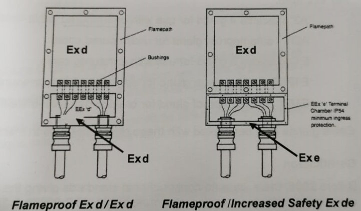
If the enclosure is indirect entry with an Ex e terminal chamber, then the glands can be single certified Exe or Exd/Exe dual certified types.
If the enclosure is indirect entry with an Ex d terminal chamber, then the glands can be certified Exd, or Exd/Exe dual certified types. Exd barrier type would be over-specified.
Direct entry method
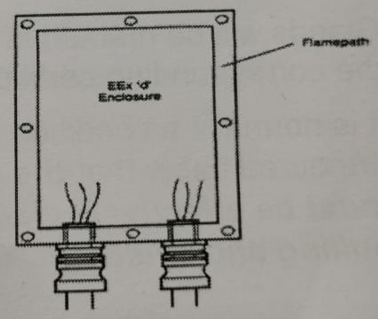
If the Exd enclosure is direct entry, then the cable glands must be certified Ex d types, selected according to the version of IEC60079-14 applicable to the particular project.
According to IEC60079-14: 2007
Select glands by using the flowchart for selection of cable gland for direct entry into a flameproof enclosure shown below.
If MICC cable is used then it must be fitted with a suitable flameproof cable entry device (i.e. Ex d MICC gland).
The flowchart applies if thermoplastic, thermosetting or elastomeric cable is used. The cable must be compact, circular and effectively filled, with extruded bedding.
Any filler must be non-hygroscopic.
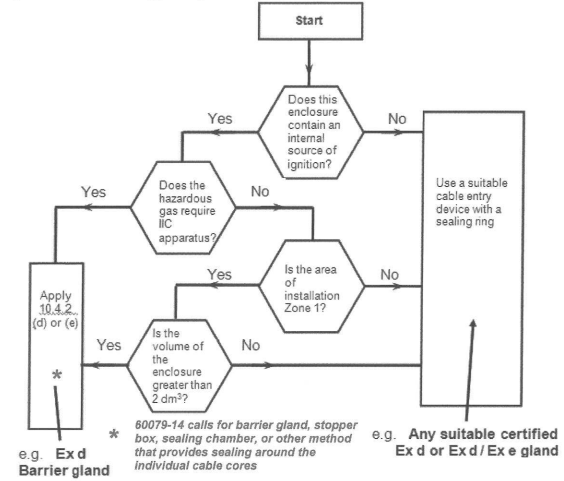
A barrier gland includes an epoxy resin compound which consolidates the cable cores and provides a pressure tight seal. In the event of an explosion in the Ex d enclosure, this seal prevents flammable gas or combustion products being forced through the spaces between the cable cores to be released in the safe area or in other Ex equipment (possibly containing a flammable atmosphere).
According to IEC60079-14: 2013. (In UK see BS EN 60079-14: 2014 and National Annexe)
- Cable must be thermoplastic, thermosetting or elastomeric, as above.
- If the cable is at least 3m in length, use certified Exd or Exd/Exe dual certified types
- If the cable is less than 3m in length, use a certified Exd barrier gland.
Also permitted is the use of MICC cable with an Ex d MICC gland, or stopper box, sealing chamber, etc. with sealing around the individual cable cores, detailed in the equipment documentation.
In the UK, the selection process from the 2013 edition has been queried as not having any experimental basis, and for that reason a National Annexe to BS EN 60079-14: 2014 recommends the continued use of the flowchart from earlier editions.
To cover the requirements of both 2007 and 2013 editions of the IEC standard, it would be necessary to fit barrier glands on all cables that are less than 3m in length, and to use the flowchart to select the appropriate gland for cables that are 3m or longer.
Glands for Ex d [i] equipment: If a flameproof enclosure contains I.S associated apparatus, then all glands entering the enclosure, including those on the IS output cable, must be Exd types according to the above procedures.
Glands for increased safety equipment ‘Ex e’
Prior to 2007, the only requirements for gland for Ex e equipment were that they meet the relevant IP rating and impact tests, and uncertified glands could be used. The 2007 edition of IEC60079-14 specified that gland must be certified glands as meeting the requirements of the IEC60079-0 standard. The 2013 edition includes a table showing that glands certified Exd or Exe may be used. This includes dual certified glands.
Glands for ‘Ex n’ equipment
Similarly, since 2007, glands for Ex n equipment must be certified, and Ex e or Ex d glands are suitable.
Dual certified Ex d/ Ex e glands are suitable for Ex d, Ex e and Ex n
Glands for Ex nR (restricted breathing) equipment may require special consideration.
Always consult the manufacturers’ installation instructions for Ex nR enclosures.
Many glands are now triple certified Ex d, Ex e and Ex nR
Glands for ‘Ex i’ equipment
Glands for Ex i equipment will generally be selected to suit the type of enclosure.
Notes:
- Terminal boxes containing IS circuits should be marked “WARNING – Intrinsically safe circuits”
- If a terminal box only has one intrinsically safe circuit, it does not need to be certified.
- If a terminal box has more than one intrinsically safe circuit, it must meet the requirement of IEC60079-0, and will therefore have to be certified (usually Ex d or Ex e).
- All terminal boxes must be suitable for the environmental conditions, usually at least IP54.
Maintaining Ingress Protection at Cable Gland Entries
The cable gland selected must suit the cable used and must maintain the ingress protection of the enclosure (which will be IP54 or greater for type ‘e’ or type ‘n’ enclosures). Where enclosures have unthreaded entries (clearance holes), IP sealing washers will always be necessary.
For threaded entries, an IP sealing washer is necessary to maintain IP54 if the wall thickness is less than 6mm.
If the wall thickness is 6mm or greater, an IP washer is not required but many be fitted to preserve the enclosure IP level if this is higher than IP54.
Ex nR
The IP sealing of restricted breathing ‘nR’ shall be such as to maintain the restricted properties of the enclosure.
Ex d
For threaded entries in flameproof enclosures, an IP washer may be fitted between the cable gland and the enclosure wall to improve ingress protection, provided that the necessary five full threads of engagement is maintained.
The IP washer is always fitted in contact with the enclosure wall. If an earth tag is fitted, this must be in contact with the gland body.
Cable glands may be marked with these references accordingly to EN 50262 / BS 6121, or with manufacturers’ type numbers.


