A typical dosing system consists of a degassing tank, pumps, and distribution system. As in the forgoing it is assumed that a comprehensive instrument and control package is employed to ensure correct and safe operation of the package.
The degassing tank in this example is combined with a shock dosing storage requirement to illustrate the problems associated with correctly sizing the tank.
It is at this point in the design of an ECP that the hydroxide by-product management must be addressed and an appreciation of the methods employed will be of assistance in evaluating a supplier’s technical proposal.
The hydroxides, Calcium Hydroxide and Magnesium Hydroxide, are insoluble in seawater and will precipitate into system blockages if not correctly managed. Similarly from this point in the system material selection has to address the corrosive nature of the hypochlorite media.
On occasions, believed to be the result of biological bloom in seawater, electrolysis of seawater can result in the formation of bubbles when the hydrogen is disentrained in the degassing tank that will discharge from the tank vent if corrective measures are not available. The commonly used precaution is to install a seawater spray to the top of the tank of a suitable pattern to cause collapse of the bubbles within the tank.
This impacts the mass balance of the system by dilution of the produced media and the mass flow rate of the spray has to be taken into account for dosing system sizing. This does not impact the weight of hypochlorite production.
Degassing / Shock Dosage Tank Sizing #
The initial criterion applied to the sizing of a degassing tank is to allow the 5 minutes residence time for the hydrogen by-product to disentrain from the media. In normal operations the flow rate from the electrolysers will be a consistent and continuous electrolyser discharge, i.e. tank infill.
In simple terms this will be a volume of one twelfth of the flow rate. In a system that is designed simply for continuous dosing with no other requirements the degassing tank size will be slightly larger than this value to allow for alarm buffer volumes and ullage for hydrogen dilution.
Given that there is a residence time control measures have to be introduced to ensure the insoluble hydroxides do not settle out. This should be emphasised in an enquiry and the means employed could include tangential inlet to the tank or tangential minimum flow lines returning from the dosing pumps, it could be an alternative to these methods to agitate the tank contents to ensure the hydroxides are maintained in suspension. Note if motorised agitators are considered the motors are likely to be in the classified area at the tank top and the media is corrosive.
Should it be decided upon to allow the hydroxides to settle out and utilise a periodic discharge to drain there are factors that should be taken into account. One is to provide a flush to the drain line after the sludge discharge to avoid solidification of the hydroxides on exposure to air, another is to ensure that the mass loss during de-sludging is taken into account on the mass balance of the system. A conical base tank would be most suitable for this application.
As illustrated above when shock dosing is employed, unless specified otherwise, a supplier will normally presume that continuous dosing is suspended during the shock dosing period(s). In this system the shock dosage volume / weight is accrued by a rate of gain on tank volume in the continuous dosing interval, i.e. the continuous dosing flow rate extracted from the tank is less than the tank infill flow rate from the electrolyser(s). The storage volume required will however be less than the shock dosage volume, the storage volume will be the shock dosage volume minus the inflow volume during the shock dosing period and it is this volume that will be added to the residence volume to largely determine the size of the tank. Again suitable buffer volumes will be added to avoid spurious level alarms due to minor variations in level and flow control.
This has been a subject of confusion however in the case of a single dosing point application the calculations are relatively simple. When a dosing system is employed to treat multiple injection points of varying dosing requirements, from a single tank, then the calculations to determine the optimum tank size become more complicated.
To illustrate this charts below example a system where the tank sizing has to accommodate 6 points of application and the daily timings of the shock dosing frequencies have been distributed to optimise on the tank size.
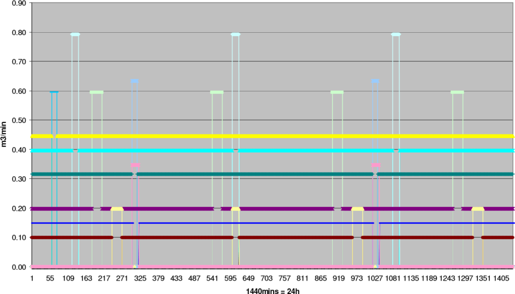
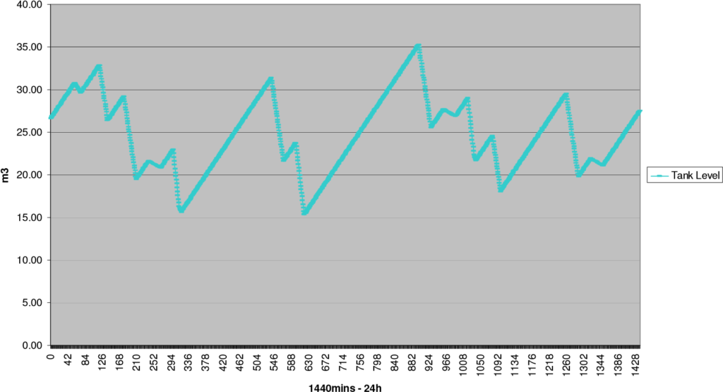
A supplier should be required to demonstrate that this key element of the package design has been evaluated to confirm that the mass balance and tank size rationalise.
Hypochlorite Distribution #
Piping and pumping installations are commonly understood disciplines and the design constraints applicable to electrochlorination systems are few but essential to address.
Of the metallic materials available for piping only Titanium is considered suitable and naturally resistant to NaOCl. This would usually represent a prohibitive cost, for example on some installations the dosing lines are >5km in length.
Other materials would include the plastics referenced above, RLCS
(Rubber lined carbon steel), HDPE (High Density Polyethylene) or GRVE (Glass reinforced vinyl ester). The latter should not be confused with GRP (Glass reinforced polyester) as this material is not resistant to NaOCl.
Other than for skid mounted packages it is generally more cost efficient to utilise a piping system that lends itself to complete fabrication on site. When, for example, RLCS is selected consequentially drawings (ISO’s) require significantly more attention to detail. Similarly the supply schedule will be extended if field joints are to be returned for factory completion.
In most instances the appropriate plastic lines for the location will be quoted to present the most economical technical proposal unless an alternative is specified.
Pump material selection is limited; Titanium and Hastelloy C have been used successfully with experience suggesting the former for consistent reliable corrosion resistance. There are also ranges of FRP pumps available that are also suitable for the media.
To accommodate the potential for sand or other wind borne material contamination of the hypochlorite solution consideration should be given to SiC/SiC mechanical seal faces on centrifugal pumps. The hydroxide content of the media has proven not to be abrasive or detrimental to these seal faces.
It is however the hydroxide content and the necessity to avoid its precipitation that dictates dosing line velocities are generally maintained between 0.75m/sec and 3 m/sec. This applies equally to pumped and gravity feed systems.
Gravity feed is used successfully where the head of the tank is adequate to maintain the required media velocity for a given length and size of piping, it should however be considered that for gravity feeding of a stored shock dose volume that the head will decrease as the tank level falls and the minimum head should be used for those calculations.
A gravity feed system should also include a weir arrangement and syphon breaker to ensure that the level in the tank does not go below the Low Low level set point as this would otherwise drain media that has not been fully detrained of hydrogen into the dosing system. Low Low set point is usually being at the level for the volume required for 5 minutes media residence in the degassing tank, which typically is a greater volume than would be used for pump loss of suction protection.
Should there be a need to continuous dose and shock dose down the same line the velocity constraints and losses should be qualified as acceptable for both dosing flow rates. This can be achieved by appropriate line sizing or an iterative process of evaluation by adjusting the product concentration. It may not be possible to achieve the velocity constraints for both dosing regimes through a single line then separate lines should be considered for confident operation without blockages from precipitated hydroxides.
An area where this is sometimes overlooked is when continuous and shock dosing pump suctions are instinctively designed with a single header to the degassing tank. Here the NPSHr for the pumps will necessitate a low velocity of 0.75-1m/sec to avoid potential cavitation and precipitation. Where the flow rate of each dosing regime will be significantly different prior evaluation of this criterion will give early indication of whether single or separate suction headers are required. This equally applies where speed control is exercised over pumps rated for the dual capacity of continuous and shock dosing regimes, if recirculation is applied the problem is not the same.
Ball valves have proven successful for seawater duty however they are not recommended to be utilised for seawater generated hypochlorite solution, where these valves are not regularly exercised the hydroxides can collect and cause difficulty in operation. Diaphragm and Butterfly valves are the better solution for this media. Flow control valves of the rotating plug or characterised port ball valves have proven successful due to their continuous modulation and the relatively high flow rate through the valves keeping the valve free of hydroxide accumulations.
What may not be obvious to all readers is that the daily demand for hypochlorite has been averaged and the ECP product will be at a consistent concentration of hypochlorite. Therefore at the same concentration to deliver a greater weight over time dosage of hypochlorite to a seawater system the flowrate of the hypochlorite has to be increased.
During a bid evaluation it may be considered that a consistent dosing flowrate of variable product concentration would be preferable. Whilst this is possible it does mean that the ECP will have to be of significantly larger generating capacity than when the demand is averaged to accommodate the maximum instantaneous hypochlorite demand.


