Hydrogen is an inherent by-product of the electrolysis of seawater and has been previously discussed as creating a hazardous area when media leakage occurs in the electrolyser area.
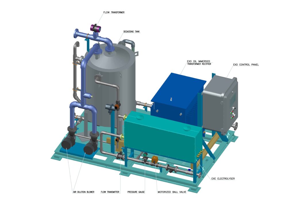
In normal operations this by-product is removed from the media to render the media suitable to be safely dosed back into seawater systems. The hydrogen can be disentrained from the media either by Hydrocyclone separation or more normally by permitting the media residence time in a degassing vessel.
It is a proven industry convention that allowing a 5 minute residence time in a properly designed tank is adequate for the removal of hydrogen from seawater that has been subject to electrolysis. Experience has shown that enquiries occasionally specify greater residency periods; this is considered an unnecessary cost adder for that purpose in isolation.
Degassing tanks can be either standalone with separate shock dosing media storage tanks or combined.
Degassing tanks can be provided as either naturally aspirated where the hydrogen is allowed to naturally disperse to atmosphere or in forced draught ventilated tanks where it is diluted with air on its escape from the surface of the media.
Hydrogen has a Lower Explosion Limit of 4% in air and in the forced draught ventilation system typically sufficient air is provided to dilute the maximum possible hydrogen product to <1% Hydrogen in air such that when exhausted to atmosphere the mixture is non hazardous. Normally 2 x 100% air supply blowers would be provided and in some instances further redundancy is provided by service air or Nitrogen purging facilities.
The implications of these choices are that with the naturally aspirated degassing tank the area around the tank top becomes Zone 0 C.
In the case of the forced draught ventilation the area around the tank vent becomes Zone II C for a maximum of 5 minutes due to the possibility of power loss to the air supply blowers when no other redundancy is installed. Presuming the control system interlocks shut down the package when loss of dilution air is detected.
This is a choice for those responsible for specifying an ECP enquiry and should be considered carefully.
Where multiple, potentially redundant, naturally aspirated tanks are employed strict attention must be applied to work permit procedures in the event of maintenance activities
Other points, or aide memoir’s, would be to ensure that forced draught installations are protected against static by the use of earthed, electrically conductive duct materials. This should be part of a risk assessment or associated with an area classification or Hazop however there could be a possibility that neither of the latter could occur during completion of the project.
If the dilution blowers are located in, and take suction from, an area that is previously classified as hazardous then it should be considered that the discharge of the degassing vent should be similarly classified. An alternative is to duct the blower suctions to an unclassified area. It has also been known for process engineers to consider any reactions between the released Hydrogen and whatever may constitute the prevailing hazardous media.
Forced draught ventilation typically would include for filters and silencers to be specified for the blowers. This would be another advantage over naturally aspirated tanks where in desert conditions wind borne sand can enter the degassing tank which can be detrimental to the dosing system equipment.
Typically, but not limited to, the choice of tanks will consist of UPVC lined GRP, GRP lined with Vinylester or GRVE. Each is satisfactory as resistant to NaOCl. Given that the forced draught ventilation system is at low pressure, typically 150-200mmwc, it is usual that both naturally aspirated and forced draught ventilation tanks are classified as atmospheric tanks. If tank level monitoring is by pressure ensure this 150mmwc is programmed into the control philosophy.
Amongst the design criteria for a degassing tank it is important that the rate of fill and empty cycles is included in the specification when shock dosing is employed, BS 4994 is a common standard employed.
For a rule of thumb the minimum flow rate for forced draught ventilation can be checked by the following calculation as suppliers could have contingencies built into their design :-
kg/h NaOCl x R x D x (Design Temp ºC + 273) = m3/h
273
kg/h NaOCl x 0.316 x 100 x (Design Temp + 273) = m3/h
273
24.75 x 0.316 x 100 x (40 + 273) = 897m3/h
273
Where
kg/h NaOCl =ECP Maximum Hypochlorite production rate kilograms /hour
(24.75kg/h from Example 2)
R = 0.316 (the ratio of Hydrogen produced at 0ºC/kg/NaOCl)
Design Temperature in ºC
(40ºC used for this example)
273 = kelvin
D is the dilution ratio of 100:1
m3/h = Volume of air required in cubic metres / hour


