The main operating design parameters for an electrolyser or electrolyser stream have been evaluated in the forgoing.

The market consists primarily of the parallel plate electrolysers for larger installations and concentric tube technology for smaller systems.
The factors that influence the selection are that the capital cost per kg is less for parallel plate systems and they can more easily generate higher concentrations of hypochlorite.
This higher concentration means that the weight of hypochlorite for a given seawater carrier stream is greater, conversely the carrier stream for a given weight of hypochlorite is less, this consequently minimises the size of the distribution system in all respects. Parallel plate technology does however necessitate the provision of acid washing facilities for periodic removal of hydroxide deposits that naturally adhere to the cell cathodes.
There are variations on a theme within the market including vertical or horizontal installations, similarly there are laminar and axial electrolyte flow paths within the electrolysers.
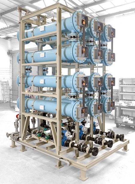
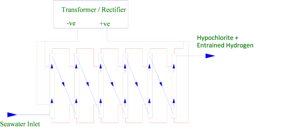
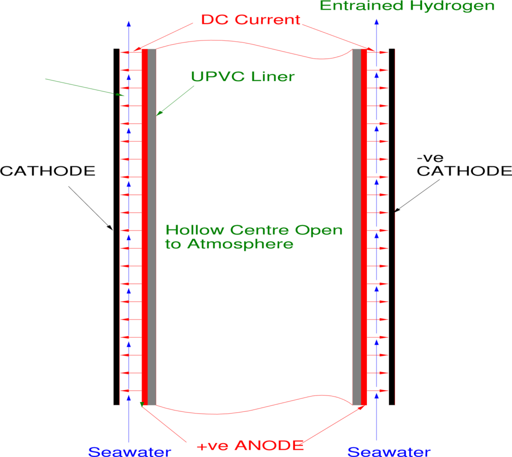
Concentric Tube technology electrolysers are illustrated in Figure 6 below. The advantage of this system is that the electrolyte flow through the annular gap between the Anode and Cathode is of a turbulence and velocity that prevents the natural adhesion of the hydroxide by-products, essentially self cleaning and has no requirements for periodic acid washing. This is an advantage where the logistics of consumables and man power availability is difficult, primarily but not exclusively offshore.
Again there are variations on a theme within the market, with vertical or horizontal installations, monopolar or bi-polar designs with wetted or non wetted inner electrode voids.
In Figures 6 & 7 below are illustrated a vertical, monopolar and non wetted inner electrode variation of concentric tube technology.


In all Electrolysers there is a necessity for the materials of construction to be both resistant to the corrosive media and also be of an electrical resistance to contain the process electrical currents and voltages.
This necessitates the utilisation of some form of plastic material within the construction and associated piping. Dependant on the ambient and seawater temperatures of the location UPVC, CPVC or ABS will be utilised. These materials are subject to a temperature pressure relationship which will dictate the design pressure of the Electrolyser assembly. The supplier will have determined the applicable design pressure for the specified design temperature and will have provided appropriate protective devices to avoid over pressurisation. Experience has shown that this might not comply with general project specifications and sympathetic consideration of this inherent limitation should be exercised by specifying authorities as there will be little if anything that a supplier can redesign to accommodate a higher than technically necessary design pressure specification.


