The Zener Barrier (also know as shunt diode barrier): #
The Zener barrier interface is normally located in the safe area, close to the boundary with the hazardous area.
The purpose of the interface is to limit the maximum energy which may be transferred to the hazardous area from the non-intrinsically safe side (input) of the circuit.
Principle Components:
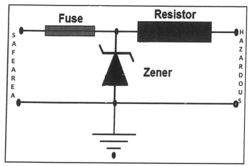
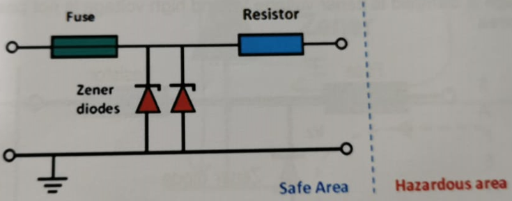
A simple zener barrier has three principal components: resistor, zener diode(s), and a fuse. The resistor limits the current into the hazardous area, the zener diode limits the voltage availableto the hazardous area, and the fuse will protect against excessive zener current.
If the barrier is connected with wrong polarity, the zener diode will conduct in the forward direction and there is a risk of blowing the fuse.
Zener Barrier Operation #
Under normal conditions, the zener is passive and allows the intrinsically safe equipment to function properly.
Zener barrier – Short circuit across output #
In the event of a short-circuit developing in the equipment in the hazardous area, or across the IS wiring, the series resistor in the zener barrier will limit the short-circuit current to a safe level so that the integrity of the system is maintained.
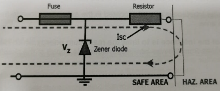
Zener barrier – invasion of high voltage #
If a voltage greater than the normal maximum voltage of the IS system invades the circuit at the input terminals of the zener barrier, the diode will conduct in the reverse direction, and shunt the resulting fault current to earth whilst clamping the voltage at the Zener level.
The return path to main earth must be of low resistance to prevent an appreciable rise in voltage on the barrier V line.
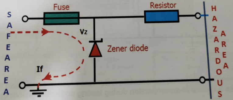
Output voltage is clamped to zener voltage Vz and high voltage is not passed to the hazardous area.
If diode fails to short (most common), the fuse will blow and open the circuit, maintaining safety.
The fuse is encapsulated along with the other components of the barrier, and the repair of zener barriers is not possible.
Infallibility of components #
Infallibility of the fuse is assured by the use of a sand-filled ceramic type capable of operating properly even when exposed to high prospective fault-currents.
Infallibility of the resistor is achieved by construction (by the use of a quality wire-wound or metal film resistor which does not operate at more than 2/3 of its rated current, voltage and power).
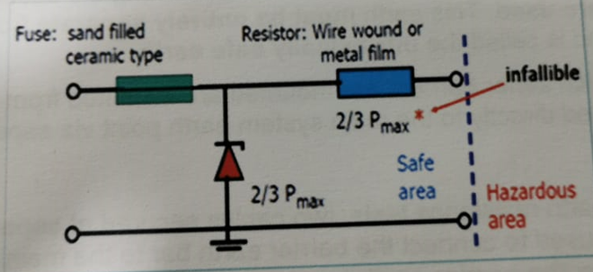
Fuse and resistor are considered to be infallible with 1.5 safety factor.
Test have shown that diodes nearly always fail to a short-circuit state which would safely blow the
fuse, but this cannot be guaranteed.
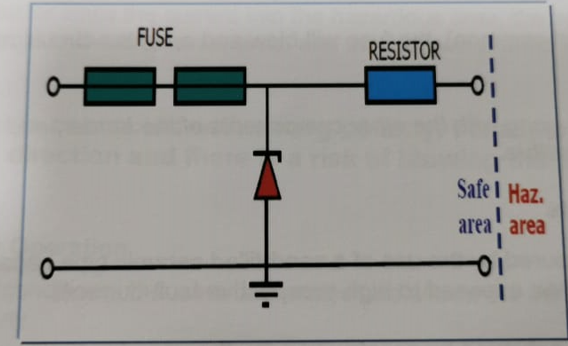
For infallibility, two or more zener diodes must be connected in parallel (and are operated within 2/3 of their rated parameters). Drawings of the barriers are usually simplified and show only one zener.
Some barriers have an additional, replaceable, lower rated fuse in series with the main fuse. This can serve as a means of disconnection during testing and commissioning.
Zener Barrier – Intrinsically safe Earthing #
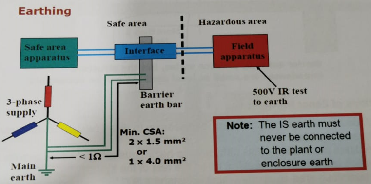
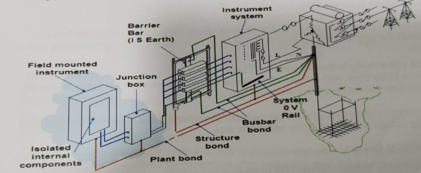
A dedicated high-integrity earth is a vital factor in maintaining the security of IS circuits when zener barriers are used. This earth must be entirely separate from plant, protective and bonding earths, and is called the intrinsically safe earth.
The rails or bars on which zener barriers are mounted are insulated from the surrounding metalwork and connected directly to the main system earth point via separate earthing conductors.
To facilitate periodical earth resistance tests, two cables secured at separate points on the bar or rail, are normally used to connect the barrier earth to the main earth point.
The resistance between the barrier earth bar and the main earth point should be less than 1Ω. A value of 0.1Ω or less can often be achieved.
The earth cable must be insulated, and the insulation undamaged, along its entire length so that contact with plant metalwork is avoided.
The earth conductors must have a rating capable of carrying the maximum fault current and have an appropriate cross-sectional area by means of:
- At least two separate 1.5mm2 (minimum) copper conductors, or
- At least one 4mm2 (minimum) copper conductor.
Note: The IS circuit in the hazardous area must be able to withstand a 500Vac or 700Vdc insulation resistance test to earth.
Earthing and Bonding #
Offshore Structure #
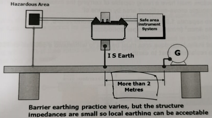
Limitations of Zener Barriers #
- A dedicated high-integrity earth is necessary to divert faut currents away from the hazardous area.
- A direct connection exits between the hazardous and safe area circuits and earth, which tends to apply constraints on the rest of the system.
- Hazardous area equipment must withstand a 500 Vac insulation resistance test to earth.


