The components of an IS installation (field equipment and associated apparatus), must to be certified items which comply with the standards.
- The documentation will include any non-certified items that are claimed as “simple”.
The equipment, together with the interconnecting cables, must be installed in accordance with –
- The manufacturer’s instructions,
- The system documentation
- IEC / BS EN60079-14
Note: If an IS circuit has both Ex ia and Ex ib equipment installed in the loop, the overall level of protection of the loop will be Ex ib.
Identification and colour – Marking of IS connection facilities etc. #
Connection facilities (terminal boxes, plugs and sockets etc.) of I.S. installations be clearly marked and identified.
Where a colour is used for such identification, it must be light blue.
To avoid confusion, light blue must not be used for other types of circuits.
Junction boxes should be marked with a label “ WARNING intrinsically safe circuits”.
Installation Requirements for I.S. Cables #
IS cables should have elastomeric or thermoplastic insulation with a minimum thickness of 0.3mm. Alternatively, mineral insulated cable may be used.
The conductors, includes the individual strands of finely stranded cables, must have a diameter not less than 0.1mm.
Separation of the individual strands of cables must be prevented by the use of core-end ferrules, for example.
The cable insulation must withstand a 500Vac or 750Vdc test, and show a min. IR of 1MΩ.
To avoid damage to sensitive IS circuits; insulation testing should only be done –
- On completion of cabling, prior to barrier installation and connection or
- Following possible damage to the cable, and after disconnecting both ends or
- Upon written request by client etc.
Mechanical Protection #
IS circuit interconnecting cables are required to have an overall sheath in order to prevent contact with cables of other circuits or earth in the event of damage.
Armouring or screening of cables for mechanical protection is not required by the standards, except for IS circuits with multi-core cables in Zone 0.
Segregation of IS and non-IS Circuits #
In both hazardous and non-hazardous areas, segregation of IS and non-IS circuits is important to avoid the possibility of higher voltages form non-IS circuits invading IS circuits.
This may be achieved by any one of the following methods-
- Adequate separation between IS circuit cables and non-IS circuit cables, or
- Positioning of the IS circuit cables such as to guard against the risk of mechanical damage, or
- The use of armoured, metal sheathed, or screened cables for either the IS or non-IS cables.
More than one IS circuit may be run in multi-core cable
Non-IS circuits are not to be run in the same multi-core as IS circuits.
Where IS cables and non-IS cables of other circuits share the same duct, bundle or tray, they must be segregated by means of an insulated or earthed metal partition.
Separation is not necessary or either the IS or the non-IS cables of the other circuit are armoured, screened or metal sheathed.
The armouring of cables should be securely bonded to the plant earth.

Multi-core cable – Unused (spare) Cores #
Where multi-core cables have one or more unused cores, the unused cores must either be
- Connected to separate terminals at both ends so that the cores are insulated from one another and earth, or
- Connected to the same earth point, if applicable, as used by the IS circuits in the cable, typically a zener barrier earth-bar. The unused cores at the other end, however, must be insulated from each other and earth by means of terminals.
For instrumentation systems, the cabling will usually be with twisted pairs of conductors. For sensors requiring three conductors, cables with ‘triples’ or ‘triads’ are available.
If only multi-pair cable were available to connect to such a sensor, then two cores should be used from one pair and one from another pair, the remaining unused core should be terminated as explained above.
Cable Screens #
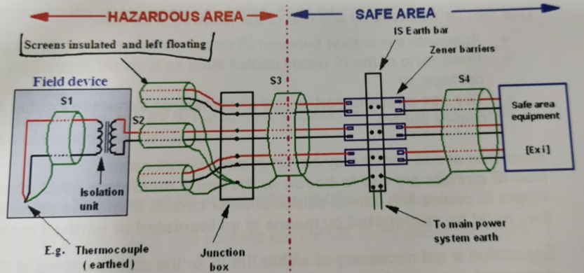
Where the IS cables have overall screens, or groups of conductors with individual screens, the screens are required to be earthed at one point only, usually in the non-hazardous area at the point specifies in the loop diagram (usually at the zener barrier earth bar).
Overall screens are required to be installed from the external metalwork, i.e. cable tray etc.
If the IS circuit is isolated from earth, connection of the screen to the equipotential bonding system should be made, at one point only, by an insulated conductor. This is to avoid the invasion of stray currents which could have incendive capability.
Each of the single pair cables is terminated in a piece of field equipment (only one shown). In each field device, the cable screen should be insulated and left electrically ‘floating’.

Induced Voltage #
IS circuits must be installed so that they are not affected by external electric or magnetic fields. Generally induced voltage in IS interconnecting cables is unlikely, but may occur if the IS cables are placed parallel and in close proximity to single-core cables carrying heavy current or to overhead power lines. Adequate segregation between the different circuits, or he use of screens and/or twisted cores, is necessary to avoid his.
Cable colour #
The sheath or core insulation of IS circuit cables may be coloured light blue in order that they may be easily identified as part of an IS circuit. Non-IS cables must not be light blue!
Marking of IS cables is not deemed necessary if either the IS or non-IS cables are armoured, screened, or metal sheathed.
Where IS circuits and non-IS circuit share he same enclosure – switchgear, control cabinet etc – appropriate measures must be taken to distinguish between the two types of circuit, and also to avoid confusion where a blue neutral conductor may be present. These include:
- Combining the IS cores in a common light blue harness,
- Labelling,
- Clear arrangement and spatial separation.
Clearance Distances #
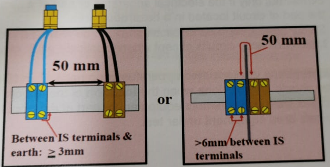
The clearance distance between the bare parts of cable conductors, connected to terminals and earth or other conducting parts should not be less than 3mm.
The clearance between the bare parts of cable conductors (connected to adjacent terminals) of separate IS circuits should not be less than 6mm.
Where IS and non-IS circuits occupy the same enclosure there must be adequate separation between the two circuit types. This may be achieved by either:
- 50mm clearance between the IS and non-IS terminals. The terminals and wiring should be positioned such that contact between the circuits is not likely should a wire from either circuit become detached. (OR)
- An insulated partition or earth metal partition located between the IS and non-IS terminals. The partition must maintain at least 50mm creepage between the terminals in all directions around the partition, or reach to within 1.5mm of the enclosure walls.
Example: IS & non-IS circuits (in same enclosure)

Glanding #
The type of glands used for I.S. cabling depends on the type of protection of the enclosure that they enter.
For example, glands for IS cables entering a flameproof enclosure would be certified Ex d or dual certified Ex d/Ex e, or may have to be Ex d barrier type if required by the criteria detailed in Unit 10.
Plastic glands for unarmoured IS cabling (for final connection to field equipment etc.) are available in light blue colour for ease of identification.


