Increased Safety Ex e Motors #
These motors are similar in appearance to standard industrial motors and inspection of the certification/rating plate is usually necessary to identify them. These motors are not designed to withstand an internal explosion, but have special design features to prevent arcs, sparks and excessive surface temperatures occurring both internally and externally.
Increased safety motors are generally intended for continuous duty only. Suitable protection features to disconnect the motor before the limiting temperature is reached are required for applications which involve frequent stopping and starting and/or long run-up times.
Under stall (locked rotor) conditions, the rotor surface temperature will normally increase faster than that of the stator windings, and hence the T-rating applies to both internal and external surface temperatures.
Under faults conditions, the motor must trip within the tE time specified on the motor data plate (see below).
The principal design features are:
- Special attention to air-gap concentricity, and to the clearance of all rotating parts.
- Impact testing of motor frame.
- The constructional standards give a limiting temperature for the motor windings,
depending on the type of insulation used (insulation class). This will be less than the
insulation temperature limit for standard machines, and will be less than the T-Class
rating for a particular motor. The limiting temperature is given in IEC60079-7 for the
different insulation classes. - Compliance with the tE characteristic. Under fault conditions, the motor must trip
within the tE time specified on the motor data plate (see below).
- Terminal blocks have specific creepage/clearance distances and locking devices.
- Minimum ingress protection to IP54 or IP44, unless covered by “special conditions of
use” for installation in a clean environment.
- Depending on the motor type and duty, special protection features may be required
in the control gear to clear faults such as overloading and locked rotor that could
give rise to excessive heating effects.
Examples:
Inverse time delta overload protection
Phase imbalance protection for delta-wound motor
Protection against arduous starting
Ex e motors are generally supplied for continuous duty only
Ex e motor must trip within tE time specified on the nameplate before the designed limiting temperature is exceeded.
tE time #
The tE time is defined as: ‘ The time taken to reach the limiting temperature from the temperature reached in normal services, when carrying the standing current IA at maximum ambient temperature.’
tE time (secs) and starting current ratio IA/IN are shown on the nameplate of an Ex e motor
Determination of tE Time #
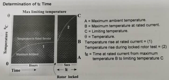
If the rotor locks as a result of a fault, motor will take full starting current and the temperature will rise rapidly and reach the limiting temperature at ‘C’ (second part of the graph).
The time taken to reach ‘C’ from ‘B’ is known as the tE time. During fault conditions the thermal overload device in the motor stater must trip the motor within this time.
Tripping Characteristic of Thermal Overload device #
The thermal overload device will be selected according to its tripping characteristic and the tE time and IA/IN current ratio marked on the motor nameplate.
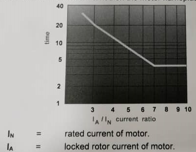
Example 1: IA/IN = 5 and tE time = 10 secs
The above characteristic would trip the motor after 8 secs, which is within the tE time and therefore acceptable.
Example 2: IA/IN = 4.5 and tE time = 8 secs
For these values the tripping time is 10 secs, which is longer than the tE time assigned to the motor. An overload device with this characteristic would not be suitable for this motor.


