Increased safety is a simple concept, but there are many detailed requirements that must be correctly implemented to result in a safe installation!
To comply with the certification, it is essential that Increased Safety enclosures are installed and maintained in accordance with the relevant Standards etc. The main points are:-
- Enclosures only certified as components (‘U’ certificate) shall not be used. There should be an equipment certificate for the complete assembly. Contents can only be modified as allowed for in the manufacturer’s documentation.
- Only components specifically approved should be fitted in the enclosure.
- All terminal screws, used and unused, should be tightened down.
- All lid and gland plate bolts must be fully tightened after installation.
- Conductor insulation should be maintained up to the metal throat of the terminal.
- Partitions should be fitted at either side of terminal linking assemblies, if the link would reduce creepage and/or clearance distances.
- Only one conductors should be fitted to each terminal side (or 2 with special ferrule).
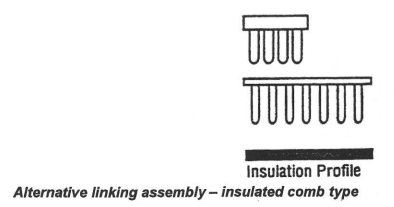
- An additional single conductor, min 1.0mm2, may be connected within the same terminal way when an insulated comb is used.
- ‘Saddle’ types are designed for two conductors. If they are used with one conductor, the wire end should be shaped into a ‘U’ to allow correct operation of the clamp.

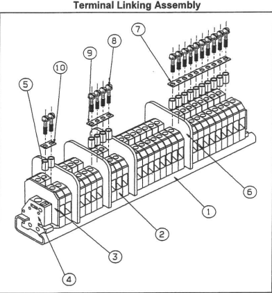
Components Approved Terminal Group
- Mounting rail;
- Terminals – certified components;
- End plate;
- End bracket;
- Distance sleeve;
- Partition;
- Copper cross-connection;
- Zinc plated screw;
- Copper cross-connection;
- Copper cross-connection.

10. ‘Slot’ type terminals permit more than one conductor, but care must be taken to ensure adequate clamping. Consult the documentation for wire sizes and quantities.
11. Care shall be taken that local hot sports are not generated. It is good practice that only the conductors form one cable entry are loomed together – in any case bunching more than 6 conductors should be avoided.
12. The individual earth continuity plates within plastic enclosures must be bonded together, and locknuts used to secure glands to the continuity plates. For clearance holes, serrated metal washers may be used between locknuts and the metallic gland plate.
13. Since the adoption of the latest standard IEC 60079-14: 2007, glands, stoppers and thread adaptors must be certified to meet the requirements of IEC 60079-0. Before 2007 glands had only to meet the Ex ‘e’ impact and IP requirements.
14. The manufacturer’s documentation must be consulted before additional cable entry holes are drilled. This will show the size, position and quality of allowable entries. Unused holes must be plugged with suitable certified stoppers.
15. When Intrinsic and Increased Safety circuits occupy the same enclosure the two types of circuit must have at least 50mm clearance between them.
16. Cable glands, conduit entries, stoppers, breathers etc must maintain the IP rating of the enclosure (minimum IP54). Threaded holes in enclosure walls or gland plates that are 6mm thick or greater will meet IP54.
17. For a threaded hole where the thickness is less than 6mm, the glands will require an IP washers and an internal locknut, in order to maintain IP54.
18. To maintain IP54 when glands etc. are to be fitted into unthreaded entry (clearance hole), an internal locknut & serrated washer, and an IP washer on the outside of the enclosure are required.
19. If the enclosure IP rating is greater than IP54, in order to maintain the enclosure rating IP washers may be required even for threaded holes in enclosure walls that are more than 6mm thick.
20. IP washers must be fitted so that they are in contact with the outside of the enclosure or gland plate.
For glands fitted with earth tags, the order of assembly is therefore:

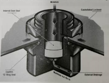
Ex e Breather Drain (component certified):
The breather drain provides a method of effectively draining any moisture within an enclosure, whilst allowing the air inside to breathe with the surrounding atmosphere.

Note: Luminaires (Light Fittings)
In the installation standard IEC60079-14 there are special requirements for light fittings (luminaries):
- Fluorescent lamps or electronic ballasts shall not be used in T5 or T6 luminaires, or where the ambient exceeds 60°C.
- Lamps (bi-pins, screw connections or tungsten lamps) using non-conductive materials with a conductive coating shall not be used unless tested with the equipment.


