Introduction #
Typical materials used for the construction of flameproof equipment include cast iron and aluminium alloys. Where corrosion resistance is required, gun metal bronze, phosphor bronze and stainless steel may be used.
Plastic materials are also used but the free internal volume must not exceed 10cm3, and the material used must pass a flammability test.
The standards specify that for flanged joints ‘there shall be no intentional gap between the surfaces’, and fives the maximum permitted average roughness of the surfaces (6.3µm).
Gap Dimensions #
Gaps will inevitably exist due to manufacturing methods, tolerances and economics, and these gaps but must not exceed the dimensions specified in the tables given in the standard for a given hazard.
Factors which influence the dimension of the gap are:
- The width of the joint
- The gas groups
- The internal volume of the enclosure
- The type of joint
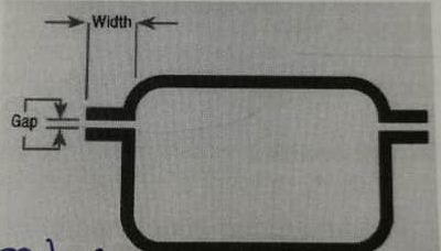
As an example, for a typical small enclosure, the maximum permitted gap for hydrogen (IIC) is 0.1mm, and for IIB gases it is 0.2mm.
Flamepath Joints #
According to the IEC 60079-1: 2014, equipment certificate number will include the “X” suffix if these are specific conditions of use that joint are not to be repaired.
Example of three joint types specified in the standard are illustrated on the next page. In a flanged joint, when the cover is properly bolted down, the machined surfaces make face-to-face contact to give a gap dimension less than that specified in the tables. This type of joint is typically used for covers of junction boxes etc.
The use of flanged joints is subject to restrictions when acetylene is the hazard.
Spigot joints will be used at junction box covers and motor end shields.
Threaded joints are used for covers joints, cable gland and conduit entries. An adequate flame path length is normally achieved with a thread engagement of five full threads, which is the maximum allowed in the standard
- Flanged joint

- Spigot joint

- Screwed joint

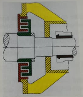
Flamepath joints types (Rotating machines)
- Cylindrical (shaft gland) joint
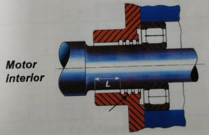
- Labyrinth joint for shafts
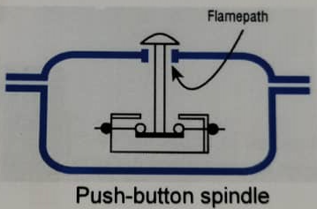
Flamepath Joints (other example) #
Flamepaths other than those at cover joints are also necessary where, for example, an actuator spindle passes through the wall of an enclosure, or where a cable gland or conduit enters an enclosure.
Simplified table of maximum allowable gaps in Ex d equipment #
| Joint type | Min. joint width mm | Maximum gap (mm) | |||||
| Volume (cm3) 500 < V < 2000 | Volume (cm3) V > 2000 | ||||||
| IIA | IIB | IIC | IIA | IIB | IIC | ||
| Flanged * | 12.5 | 0.30 | 0.20 | 0.04 | 0.20 | 0.15 | – |
| 25 | 0.40 | 0.20 | 0.04 | 0.40 | 0.20 | 0.04 | |
| Spigot | 12.5 | N/A | N/A | 0.18 | N/A | N/A | 0.18 |
| 25 | N/A | N/A | 0.18 | N/A | N/A | 0.18 | |
| 40 | 0.40 | 0.20 | 0.20 | 0.40 | 0.20 | 0.20 | |
| Cylindrical (for bearings) | 12.5 | 0.45 | 0.30 | 0.25 | 0.30 | 0.20 | – |
| 25 | 0.60 | 0.40 | 0.25 | 0.60 | 0.30 | 0.25 | |
| 40 | 0.75 | 0.45 | 0.30 | 0.75 | 0.40 | 0.30 |
More detailed table of maximum allowable gaps in Ex d Equipment #
| Type of Joint | Minimum width of joint L mm | Maximum gap mm | |||||||||||||||
| For a volume cm3 V ≤ 100 | For a volume cm3 100 < V ≤ 500 | For a volume cm3 500 < V ≤ 2 000 | For a volume cm3 2 000 < V ≤ 5 750 | For a volume cm3 V > 5 750 | |||||||||||||
| I | IIA | IIB | I | IIA | IIB | I | IIA | IIB | I | IIA | IIB | I | IIA | IIB | |||
| Flanged, cylindrical or spigot joints | 6 | 0.30 | 0.30 | 0.20 | – | – | – | – | – | – | – | – | – | – | – | – | |
| 9.5 | 0.35 | 0.30 | 0.20 | 0.35 | 0.30 | 0.20 | 0.80 | 0.80 | 0.80 | – | 0.08 | 0.08 | – | 0.08 | – | ||
| 12.5 | 0.40 | 0.30 | 0.20 | 0.40 | 0.30 | 0.20 | 0.40 | 0.30 | 0.20 | 0.40 | 0.20 | 0.15 | 0.40 | 0.20 | 0.15 | ||
| 25 | 0.50 | 0.40 | 0.20 | 0.50 | 0.40 | 0.20 | 0.50 | 0.40 | 0.20 | 0.50 | 0.40 | 0.20 | 0.50 | 0.40 | 0.20 | ||
| Cylindrical joints for shaft glands of rotating electrical machines with: | Sleeve bearings | 6 | 0.30 | 0.30 | 0.20 | – | – | – | – | – | – | – | – | – | – | – | – |
| 9.5 | 0.35 | 0.30 | 0.20 | – | – | – | – | – | – | – | – | – | – | – | – | ||
| 12.5 | 0.40 | 0.35 | 0.25 | 0.40 | 0.20 | – | 0.40 | 0.30 | 0.20 | 0.40 | 0.20 | – | 0.40 | 0.20 | – | ||
| 25 | 0.50 | 0.40 | 0.30 | 0.50 | 0.40 | 0.20 | 0.50 | 0.490 | 0.25 | 0.50 | 0.40 | 0.20 | 0.50 | 0.40 | 0.20 | ||
| 40 | 0.60 | 0.50 | 0.40 | 0.60 | 0.50 | 0.25 | 0.60 | 0.50 | 0.30 | 0.60 | 0.50 | 0.25 | 0.60 | 0.50 | 0.25 | ||
| Rolling-element bearings | 6 | 0.45 | 0.45 | 0.30 | – | – | – | – | – | – | – | – | – | – | – | – | |
| 9.5 | 0.50 | 0.45 | 0.35 | – | – | – | – | – | – | – | – | – | – | – | – | ||
| 12.5 | 0.60 | 0.50 | 0.40 | 0.60 | 0.30 | 0.20 | 0.60 | 0.45 | 0.30 | 0.60 | 0.30 | 0.20 | 0.60 | 0.30 | 0.20 | ||
| 25 | 0.75 | 0.60 | 0.45 | 0.75 | 0.60 | 0.30 | 0.75 | 0.60 | 0.40 | 0.75 | 0.60 | 0.30 | 0.75 | 0.60 | 0.30 | ||
| 40 | 0.80 | 0.75 | 0.60 | 0.80 | 0.75 | 0.40 | 0.80 | 0.75 | 0.45 | 0.80 | 0.75 | 0.40 | 0.80 | 0.75 | 0.40 |


